Electronic Component Symbols
+3
Vers
denden
Admin
7 posters
 AdminAdmin
- Posts : 18
Join date : 2018-08-01 
 Electronic Component Symbols
Wed Aug 15, 2018 2:30 pm
Electronics is a branch of an engineering, which deals with electronic and electrical circuits like Integrated circuits. The electronic circuit is defined as, it is a combination of various electronic components that allows the flow of electric current. The electronic components consist of two or more terminals, that are used to connect one component to another component to design a circuit diagram. The electronic components are soldered on circuit boards to make a system.

The electronic circuit symbols mainly involve wires, power supplies, resistors, capacitors, diodes, transistors, meters, switches, sensors, logic gates, audio devices and other components.
Wires
A wire is a two terminal, single and flexible material, that allows the flow of power through it. These are mainly used to connect the power supplies to PCB( Printed Circuit Board) and in between the components. The different types of wires will be as

Wires: A single wire with two terminals will pass the current from one component to another.
Wires Jointed: When two or more wires are connected with each other that is called as wires jointed. The jointing or shorted of wires at one point is indicates the “blob”.
Wires not Jointed: In complex circuit diagrams, some wires may not connect with others, in this case bridging is commonly utilized.
Power Supplies
A Power supply/ power supply unit is an electronic device, that supplies electric energy to an electrical load. The flow of an electric current will be measured in terms of Watts. The function of power supply is, it converts energy from one form to another according to our requirement. The various types of power supplies are

Cell Circuit: Supplies electrical energy from larger terminal (+) positive sign.
Battery Circuit: A Battery is two or more cells, the function of battery circuit is same as cell circuit.
DC Circuit Symbol: Direct current (DC) always flows in one direction.
AC Circuit Symbol: AC (Alternating Current) flows periodically reverses direction.
Fuse Circuit: The fuse will flow sufficient current and it is used to provide over current protection.
Transformer: It is used to produce AC power supply, energy is transferred in between primary and secondary coils in the form mutual inductance.
Solar cell: It will convert light energy into electrical energy.
Earth: It supplies the 0V to the circuit that will connect to the earth.
Voltage Source: It will supply voltage to the circuit elements.
Current Source: It will supply current to the circuit elements.
AC Voltage Source: It will supply AC voltage to the circuit elements.
Controlled Voltage Source: It generates controlled voltage to the circuit elements.
Controlled Current Source: It generates controlled current to the circuit elements.
Resistors
A Resistor is a passive element that opposes current flow in a circuit. It is a two terminal element, dissipates its energy in the form of heat. The resistor will damage due to the overflow of electric current through it. Resistance is measured in units of ohms and resistance, resistor color code calculator is used to calculate the value of resistor according to its colors.

Resistor: It is a two terminal component, that restricts the flow of current.
Rheostat: It is a two terminal component, that is used to adjust the flow of current.
Potentiometer: Potentiometer is a three terminal component that will adjust the voltage flow in the circuit.
Preset: Preset is a low cost adjustable resistor that operates by using small tools like Screwdrivers.
Capacitors
A Capacitor generally referred as condenser, it is a two terminal passive component that will capable of storing energy in the form of electricity. These are the rechargeable batteries mainly used in power supply. In the capacitors, electrical plates differ by a dielectric medium and these are acts like a filter that allows only AC signals and blocks DC Signals. The capacitors are classified into various types that are discussed below
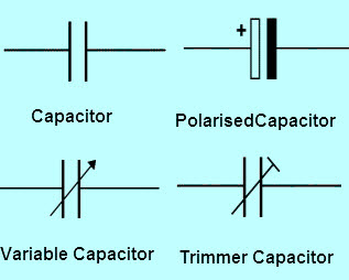
Capacitor: A capacitor is used to store the energy in electrical form.
Polarized Capacitor: Stores electrical energy these must be a one way round.
Variable Capacitor: These capacitors are used to control the capacitance by adjusting the Knob.
Trimmer Capacitor: These capacitors are used to control the capacitance by using Screwdriver or similar tools.
Diodes
A Diode is an electronic component with two terminals that are anode and cathode. It allows electron current flow from cathode to anode but it blocks another direction. The diode will have low resistance in one direction and high resistance in another direction.The diodes are classified into various types that are discussed below

Diode: A diode allows the current flow in one direction.
Light Emitting Diode: It will emit the light when the electric current flows through it.
Zener Diode: It will allow a constant electric current after the breakdown voltage.
Photo Diode: Photo diode will convert light into respective current or voltage.
Tunnel Diode: Tunnel diode is used for very high speed operations.
Schottky Diode: Schottky diode is for forward low voltage drop.
Transistors
The transistors are invented in 1947 at Bell Laboratories to replace vacuum tubes, that it will control the flow of current and voltage in the circuits. It is a three terminal device and amplifies the current, transistors plays an important role in all modern electronics.

NPN transistor: A P-type doped semiconductor material is placed in between two N-type semiconductor materials. The terminals are emitter, base and collector.
PNP transistor: A N-type doped semiconductor material is placed in between two P-type semiconductor materials. The terminals are emitter, base and collector.
Photo transistor: It is similar to bipolar transistors, but it converts light to current.
Field Effect Transistor: FET control the conductivity with the help of electric field.
N-channel JFET: The Junction Field Effect Transistors are simple of FET for switching.
P-channel JFET: P-type semiconductor is placed in between N-type junctions.
Enhancement MOSFET: Similar to DMOSFET but absence of conducting channel.
Depletion MOSFET: The current flows from source to drain terminal.
Meters
A Meter is an instrument used for measuring voltage and current flow in electrical and electronic components. These are used to measure resistance and capacitance of the electronic components.

Voltmeter: It is used to measure voltage.
Ammeter: It is used to measure current.
Galvanometer: It is used to measure small currents.
Ohmmeter: It is used to measure the electrical resistance of a particular resistor.
Oscilloscope: It is used to measure voltage with respect to time for signals.
Switches
A Switch is an electrical/electronic component that will connect electrical circuits when the switch is closed, otherwise it will break an electrical circuit when the switch is open.

Push switch: It will pass the current flow when the switch is pressed.
Push to break switch: It will block the current flow when the switch is pressed.
Single pole single throw switch (SPST): Simply, it is an ON/OFF switch allows flow only when switch is in ON.
Single pole double throw switch (SPDT): In this type of switch current flows in two directions.
Double pole single throw switch (DPST): It is a dual SPST switch, mainly used for electrical lines.
Double pole double throw switch (DPDT): It is a dual SPDT switch.
Relay: A relay is a simple electromechanical switch made up of an electromagnet & a set of contacts.These are found hidden in all sorts of devices.
Audio Devices
These devices convert an electric signal into sound signals and vice versa, which will be audible to humans. These are input/output electronic components in the circuit diagram.

Microphone: converts sound or noise signal to an electrical signal.
Earphone: converts electrical signal to sound signal.
Loudspeaker: converts electrical signal to sound signal but it will amplified version.
Piezo- transducer: converts flows of electrical energy to sound signal.
Bell: converts electrical signal to sound signal.
Buzzer: converts electrical signal to sound signal.
Sensors
Sensors will sense or detect moving objects and devices, it will convert those signals into electrical or optical. For example a temperature sensor is used sense temperature present in the room. The various types of sensors are

Light dependent resistor: These sensors will sense light.
Thermistor: These sensors will sense heat or temperature.
Logic Gates
Logic gates are the main building blocks in the digital circuits, logic gates will have two or three inputs and a single output. The output produced by logic gates based on certain logic. Basic Logic gate values represent in binary if we observe their truth tables.

AND Gate: The output value is HIGH, when two inputs are HIGH.
OR Gate: The output value is HIGH, when one of the inputs is HIGH.
NOT Gate: The output is complement of the input.
NAND Gate: The complement of the AND gate is a NAND gate.
NOR Gate: The complement of the OR gate is a NAND gate.
X-OR Gate: The output is HIGH when an odd number of HIGH occurs in its inputs.
X-NOR Gate: The output is HIGH when an even number of HIGH occurs in its inputs.
Other Components
These are the some of the electronic / electrical components that are utilized in electronic circuit or electrical circuit design.

Lighting Lamp: It is a bulb that will glow when certain current flows.
Indicator Lamp: It will convert electricity to light.
Inductor: It will generate a magnetic field when current flows through it.
Antenna: It is used to transmit and Receive the radio signals.
Thus, this is all about electronic circuit symbols . Hope this article gives you a knowledgeable information by reading above article.
The electronic circuit symbols mainly involve wires, power supplies, resistors, capacitors, diodes, transistors, meters, switches, sensors, logic gates, audio devices and other components.
Wires
A wire is a two terminal, single and flexible material, that allows the flow of power through it. These are mainly used to connect the power supplies to PCB( Printed Circuit Board) and in between the components. The different types of wires will be as
Wires: A single wire with two terminals will pass the current from one component to another.
Wires Jointed: When two or more wires are connected with each other that is called as wires jointed. The jointing or shorted of wires at one point is indicates the “blob”.
Wires not Jointed: In complex circuit diagrams, some wires may not connect with others, in this case bridging is commonly utilized.
Power Supplies
A Power supply/ power supply unit is an electronic device, that supplies electric energy to an electrical load. The flow of an electric current will be measured in terms of Watts. The function of power supply is, it converts energy from one form to another according to our requirement. The various types of power supplies are
Cell Circuit: Supplies electrical energy from larger terminal (+) positive sign.
Battery Circuit: A Battery is two or more cells, the function of battery circuit is same as cell circuit.
DC Circuit Symbol: Direct current (DC) always flows in one direction.
AC Circuit Symbol: AC (Alternating Current) flows periodically reverses direction.
Fuse Circuit: The fuse will flow sufficient current and it is used to provide over current protection.
Transformer: It is used to produce AC power supply, energy is transferred in between primary and secondary coils in the form mutual inductance.
Solar cell: It will convert light energy into electrical energy.
Earth: It supplies the 0V to the circuit that will connect to the earth.
Voltage Source: It will supply voltage to the circuit elements.
Current Source: It will supply current to the circuit elements.
AC Voltage Source: It will supply AC voltage to the circuit elements.
Controlled Voltage Source: It generates controlled voltage to the circuit elements.
Controlled Current Source: It generates controlled current to the circuit elements.
Resistors
A Resistor is a passive element that opposes current flow in a circuit. It is a two terminal element, dissipates its energy in the form of heat. The resistor will damage due to the overflow of electric current through it. Resistance is measured in units of ohms and resistance, resistor color code calculator is used to calculate the value of resistor according to its colors.
Resistor: It is a two terminal component, that restricts the flow of current.
Rheostat: It is a two terminal component, that is used to adjust the flow of current.
Potentiometer: Potentiometer is a three terminal component that will adjust the voltage flow in the circuit.
Preset: Preset is a low cost adjustable resistor that operates by using small tools like Screwdrivers.
Capacitors
A Capacitor generally referred as condenser, it is a two terminal passive component that will capable of storing energy in the form of electricity. These are the rechargeable batteries mainly used in power supply. In the capacitors, electrical plates differ by a dielectric medium and these are acts like a filter that allows only AC signals and blocks DC Signals. The capacitors are classified into various types that are discussed below
Capacitor: A capacitor is used to store the energy in electrical form.
Polarized Capacitor: Stores electrical energy these must be a one way round.
Variable Capacitor: These capacitors are used to control the capacitance by adjusting the Knob.
Trimmer Capacitor: These capacitors are used to control the capacitance by using Screwdriver or similar tools.
Diodes
A Diode is an electronic component with two terminals that are anode and cathode. It allows electron current flow from cathode to anode but it blocks another direction. The diode will have low resistance in one direction and high resistance in another direction.The diodes are classified into various types that are discussed below
Diode: A diode allows the current flow in one direction.
Light Emitting Diode: It will emit the light when the electric current flows through it.
Zener Diode: It will allow a constant electric current after the breakdown voltage.
Photo Diode: Photo diode will convert light into respective current or voltage.
Tunnel Diode: Tunnel diode is used for very high speed operations.
Schottky Diode: Schottky diode is for forward low voltage drop.
Transistors
The transistors are invented in 1947 at Bell Laboratories to replace vacuum tubes, that it will control the flow of current and voltage in the circuits. It is a three terminal device and amplifies the current, transistors plays an important role in all modern electronics.
NPN transistor: A P-type doped semiconductor material is placed in between two N-type semiconductor materials. The terminals are emitter, base and collector.
PNP transistor: A N-type doped semiconductor material is placed in between two P-type semiconductor materials. The terminals are emitter, base and collector.
Photo transistor: It is similar to bipolar transistors, but it converts light to current.
Field Effect Transistor: FET control the conductivity with the help of electric field.
N-channel JFET: The Junction Field Effect Transistors are simple of FET for switching.
P-channel JFET: P-type semiconductor is placed in between N-type junctions.
Enhancement MOSFET: Similar to DMOSFET but absence of conducting channel.
Depletion MOSFET: The current flows from source to drain terminal.
Meters
A Meter is an instrument used for measuring voltage and current flow in electrical and electronic components. These are used to measure resistance and capacitance of the electronic components.
Voltmeter: It is used to measure voltage.
Ammeter: It is used to measure current.
Galvanometer: It is used to measure small currents.
Ohmmeter: It is used to measure the electrical resistance of a particular resistor.
Oscilloscope: It is used to measure voltage with respect to time for signals.
Switches
A Switch is an electrical/electronic component that will connect electrical circuits when the switch is closed, otherwise it will break an electrical circuit when the switch is open.
Push switch: It will pass the current flow when the switch is pressed.
Push to break switch: It will block the current flow when the switch is pressed.
Single pole single throw switch (SPST): Simply, it is an ON/OFF switch allows flow only when switch is in ON.
Single pole double throw switch (SPDT): In this type of switch current flows in two directions.
Double pole single throw switch (DPST): It is a dual SPST switch, mainly used for electrical lines.
Double pole double throw switch (DPDT): It is a dual SPDT switch.
Relay: A relay is a simple electromechanical switch made up of an electromagnet & a set of contacts.These are found hidden in all sorts of devices.
Audio Devices
These devices convert an electric signal into sound signals and vice versa, which will be audible to humans. These are input/output electronic components in the circuit diagram.
Microphone: converts sound or noise signal to an electrical signal.
Earphone: converts electrical signal to sound signal.
Loudspeaker: converts electrical signal to sound signal but it will amplified version.
Piezo- transducer: converts flows of electrical energy to sound signal.
Bell: converts electrical signal to sound signal.
Buzzer: converts electrical signal to sound signal.
Sensors
Sensors will sense or detect moving objects and devices, it will convert those signals into electrical or optical. For example a temperature sensor is used sense temperature present in the room. The various types of sensors are
Light dependent resistor: These sensors will sense light.
Thermistor: These sensors will sense heat or temperature.
Logic Gates
Logic gates are the main building blocks in the digital circuits, logic gates will have two or three inputs and a single output. The output produced by logic gates based on certain logic. Basic Logic gate values represent in binary if we observe their truth tables.
AND Gate: The output value is HIGH, when two inputs are HIGH.
OR Gate: The output value is HIGH, when one of the inputs is HIGH.
NOT Gate: The output is complement of the input.
NAND Gate: The complement of the AND gate is a NAND gate.
NOR Gate: The complement of the OR gate is a NAND gate.
X-OR Gate: The output is HIGH when an odd number of HIGH occurs in its inputs.
X-NOR Gate: The output is HIGH when an even number of HIGH occurs in its inputs.
Other Components
These are the some of the electronic / electrical components that are utilized in electronic circuit or electrical circuit design.
Lighting Lamp: It is a bulb that will glow when certain current flows.
Indicator Lamp: It will convert electricity to light.
Inductor: It will generate a magnetic field when current flows through it.
Antenna: It is used to transmit and Receive the radio signals.
Thus, this is all about electronic circuit symbols . Hope this article gives you a knowledgeable information by reading above article.
 dendenGuru
- Posts : 10
Join date : 2018-08-19
Re: Electronic Component Symbols
Sun Aug 19, 2018 5:24 pm
This is very informative and will surely help to the electrical students like me.
- AdminAdmin
- Posts : 18
Join date : 2018-08-01
Re: Electronic Component Symbols
Sun Aug 19, 2018 5:33 pm
Thanks for joining my forum denden. I'm glad to hear that. I will make sure to keep you updated for further topics we can discuss.denden wrote:This is very informative and will surely help to the electrical students like me.
 VersGuru
- Posts : 10
Join date : 2018-08-19
Re: Electronic Component Symbols
Wed Aug 22, 2018 3:28 pm
What is the use of electronic component symbols?
- VersGuru
- Posts : 10
Join date : 2018-08-19
Re: Electronic Component Symbols
Wed Aug 22, 2018 3:30 pm
what are the components symbol that you can frequently see in a circuit?
- AdminAdmin
- Posts : 18
Join date : 2018-08-01
Re: Electronic Component Symbols
Wed Aug 22, 2018 3:37 pm
Electronic component symbols are used in a schematic diagram of a circuit to represent various electrical and electronic devices or functions, such as wires, batteries, resistors, and transistors.Vers wrote:What is the use of electronic component symbols?
- AdminAdmin
- Posts : 18
Join date : 2018-08-01
Re: Electronic Component Symbols
Wed Aug 22, 2018 3:43 pm
In a basic circuit there always be a battery which serve as a source or a power aside from that a resistor, capacitor, transistor and a diode are always present as well.Vers wrote:what are the components symbol that you can frequently see in a circuit?
- margsGuru
- Posts : 10
Join date : 2018-08-22
Re: Electronic Component Symbols
Wed Aug 22, 2018 4:43 pm
I haven't heard of Schottky Diode. Where can you use that?
- margsGuru
- Posts : 10
Join date : 2018-08-22
Re: Electronic Component Symbols
Wed Aug 22, 2018 4:49 pm
Rheostat and preset symbol is both variable resistor and has a quite similar symbol. can you differentiate the two?
- margsGuru
- Posts : 10
Join date : 2018-08-22
Re: Electronic Component Symbols
Wed Aug 22, 2018 4:56 pm
How many types of electronic components are there?
- margsGuru
- Posts : 10
Join date : 2018-08-22
Re: Electronic Component Symbols
Wed Aug 22, 2018 4:57 pm
What is the meaning of active components?
- margsGuru
- Posts : 10
Join date : 2018-08-22
Re: Electronic Component Symbols
Wed Aug 22, 2018 4:57 pm
How about the passive components?
- margsGuru
- Posts : 10
Join date : 2018-08-22
Re: Electronic Component Symbols
Wed Aug 22, 2018 4:59 pm
Where do we use logic gates?
 zekmayor09Guru
- Posts : 10
Join date : 2018-08-22
Re: Electronic Component Symbols
Wed Aug 22, 2018 11:12 pm
Active Components is a device that has an analog electronic filter with the ability to amplify a signal or produce a power gain.
- zekmayor09Guru
- Posts : 10
Join date : 2018-08-22
Re: Electronic Component Symbols
Wed Aug 22, 2018 11:22 pm
we will be using logic gates in our digital electronic circuits so that we can operate one or more input signals to produce standard output.
- zekmayor09Guru
- Posts : 10
Join date : 2018-08-22
Re: Electronic Component Symbols
Wed Aug 22, 2018 11:40 pm
In order for a circuit to be properly called electronic, it must contain at least one active device. Components incapable of controlling current by means of another electrical signal are called passive devices. Resistors, capacitors, inductors, transformers, and even diodes are all considered passive devices.
- zekmayor09Guru
- Posts : 10
Join date : 2018-08-22
Re: Electronic Component Symbols
Wed Aug 22, 2018 11:43 pm
They have 2 types of electronic components which are the Active and Passive Electronic Components.
- puralan jomarkGuru
- Posts : 10
Join date : 2018-08-23
Re: Electronic Component Symbols
Thu Aug 23, 2018 9:55 am
why the variable reistor and variable capacitor have the same symbols
- puralan jomarkGuru
- Posts : 10
Join date : 2018-08-23
Re: Electronic Component Symbols
Thu Aug 23, 2018 9:57 am
it is used to understand the schematic diagramVers wrote:What is the use of electronic component symbols?
- katieeGuru
- Posts : 10
Join date : 2018-08-23
Re: Electronic Component Symbols
Thu Aug 23, 2018 12:33 pm
It does not have the same symbol. variable resistor has a rectangle shape figure while variable capacitor has a two vertical parallel lines though they both have an arrow pointed and place in the same direction because that indicates the variable.puralan jomark wrote:why the variable reistor and variable capacitor have the same symbols
- katieeGuru
- Posts : 10
Join date : 2018-08-23
Re: Electronic Component Symbols
Thu Aug 23, 2018 12:37 pm
Passive Components are electronic components that do not require a Source of Energy to perform their intended functions. For example a resistor that is a passive componentmargs wrote:How about the passive components?
- katieeGuru
- Posts : 10
Join date : 2018-08-23
Re: Electronic Component Symbols
Thu Aug 23, 2018 12:49 pm
Active components include amplifying components such as transistors, triode vacuum tubes (valves), and tunnel diodes. Passive components can't introduce net energy into the circuit. Passive components include two-terminal components such as resistors, capacitors, inductors, and transformers.zekmayor09 wrote:They have 2 types of electronic components which are the Active and Passive Electronic Components.
- katieeGuru
- Posts : 10
Join date : 2018-08-23
Re: Electronic Component Symbols
Thu Aug 23, 2018 12:53 pm
Rheostat is an adjustable or variable resistor. It is used to control the electrical resistance of a circuit without interrupting the flow of current .A preset resistor is a smaller PCB mounted version of a potentiometer. These are useful where adjustment or configuration of a circuit needs to be made but such adjustment only occurs during building a circuit, not during normal usemargs wrote:Rheostat and preset symbol is both variable resistor and has a quite similar symbol. can you differentiate the two?
- katieeGuru
- Posts : 10
Join date : 2018-08-23
Re: Electronic Component Symbols
Thu Aug 23, 2018 12:54 pm
The Schottky diode, also known as Schottky barrier diode or hot-carrier diode, is a semiconductor diode formed by the junction of a semiconductor with a metal. It has a low forward voltage drop and a very fast switching action.margs wrote:I haven't heard of Schottky Diode. Where can you use that?
- katieeGuru
- Posts : 10
Join date : 2018-08-23
Re: Electronic Component Symbols
Thu Aug 23, 2018 12:57 pm
An electronic component symbol is a pictogram used to represent various electrical and electronic devices or functions, such as wires, batteries, resistors, and transistors.puralan jomark wrote:it is used to understand the schematic diagramVers wrote:What is the use of electronic component symbols?
Permissions in this forum:
You cannot reply to topics in this forum|
|
|